Wiring diagram of radar level gauge
"Wire system" refers to the number of wires used for power supply and standard signal transmission of the instrument. The name of the several-wire system only came into being after the birth of the two-wire transmitter. This is the result of the wide application of electronic amplifiers in meters. The essence of amplification is an energy conversion process, which is inseparable from power supply. Therefore, the first to appear is a four-wire transmitter, that is, two wires are responsible for the supply of power, and the other two wires are responsible for outputting the converted and amplified signals (such as voltage, current, etc.)
There are several ways to connect the radar level gauge as follows:
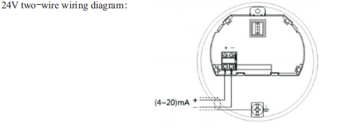
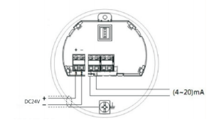
1.(4~20) mA/HART (two-wire)Power supply and output current signals share a two-core
shielded cable. Specific supply voltage ranges see technical data. For intrinsically safe power supply, guard grating should be added between supply power and the instrument.
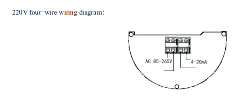
(4~20) mA/HART (four-wire) Power supply and current signal is separated by individually using a cable. Specific supply voltage ranges see technical data.
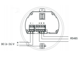
RS485/Modbus The supply voltage and Modbus signal line respectively use a shield cable. Specific supply voltage ranges see technical data.