Instrument knowledge| Installation and use of Insertion intelligent electromagnetic flow meter
There are many types of electromagnetic flow meters, which can be divided into pipeline electromagnetic flow meters and plug-in electromagnetic flow meters according to different installation methods. The plug-in electromagnetic flow meter retains the advantages of the previous pipeline electromagnetic flow meter, but also overcomes the shortcomings of the pipeline electromagnetic flow meter on large-diameter pipelines, such as difficulty in installation, high cost, and difficulty in periodic calibration. It is widely used in tap water, steel and iron. , Petroleum, chemical industry, industry, water conservancy and other sectors of conductive fluids, as well as acid, alkali, salt and other corrosive conductive liquid flow measurement.
Let us take a look at the plug-in electromagnetic flow meter together.
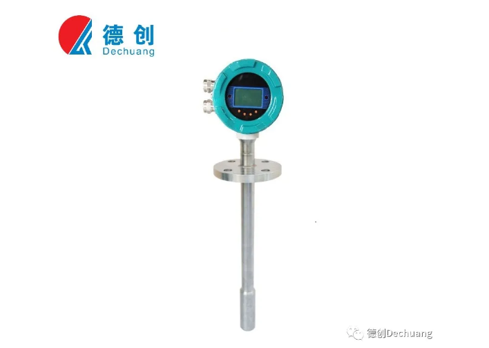
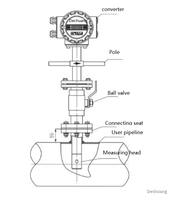
The basic structure of the plug-in electromagnetic flowmeter is as follows:
1. Choice of installation environment
Keep away from equipment with strong electromagnetic fields as much as possible, such as high-power motors, high-power transformers, etc.
There should be no strong vibration at the installation site, the pipes should be firmly fixed, and the ambient temperature should not change too much.
The installation environment should be easy to install and maintain.
2 .Choice of installation location
The installation location must ensure that the pipe is always filled with the fluid being tested
Choose a place where the flow of fluid is small, that is, it should be far away from local resistance parts such as pumps, valves, and elbows.
The diameter or circumference of the side tube is easy to measure, and the ellipse should be small.
Avoid measuring negative pressure on site.
When measuring two-phase (solid, liquid, gas, liquid) fluid, the plug-in electromagnetic flowmeter should be selected where it is not easy to cause phase separation.
3 .opening requirements
There are two straight pipe sections on site: the vertical straight pipe section and the horizontal straight pipe section. Measure the length of the two straight pipe sections. The larger one is preferred;
Try not to have a bypass pipe in the straight pipe section. If there is, the smaller the diameter, the better. There is no bypass pipe preferred.
The installation location is far away from solenoid valves, pumps, frequency converters, and the longest distance is preferred;
Select the straight pipe section, and open holes atthe ratio of straight pipe section 3:7, the upstream ratio of the opening is 7 and the downstream ratio is 3, that is, the longer the front straight pipe section of the flowmeter, the better;
Note: The opening position is far away from the solenoid valve, pump, inverter, as the first priority.
4. Welding of the mounting base
The axis of the installation base pipe and the axis of the tested pipe are perpendicular to each other;
Conventional stainless steel flanges are flat welded with stainless steel electrodes, and PVC pipes can be welded with hot melt adhesive tape. After welding, ensure that the flange end face is parallel to the pipe axis, and the welding seam is firm, and can withstand 1.6MPa pressure without leakage;
The opening size of the pipe under test is the same as the outer diameter of the installation base.
5. Sensor installation
The sensor should be installed perpendicular to the measuring pipeline, and the angle between the sensor and the vertical diameter of the pipe section when inserted into the pipeline should be less than 5°. It is suitable for measuring clean media with small vibrations in the pipeline.
There are two ways to insert the sensor: one is to insert it on the central axis of the pipe under test (that is, 1/2 times the pipe diameter); the other is to insert it into the inner wall of the pipe at 1/4 of the pipe.
Turn off the upstream flow control valve or use low-pressure water supply, install the DN50 ball valve on the base, pay attention to the long cavity of the ball valve upwards, check whether the ball valve can be fully opened and fully closed, if there is any problem, repair it. Install the compression threaded seat, compression nut and rubber sealing ring on the ball valve, loosen the positioning screw and compression nut, and insert the sensor insertion rod into the tested pipe through the ball valve. After the insertion depth meets the requirements, tighten the nut and the positioning screw. At the same time, pay attention to the direction of the sensor direction indicator pole to be consistent with the fluid flow.
6. ground
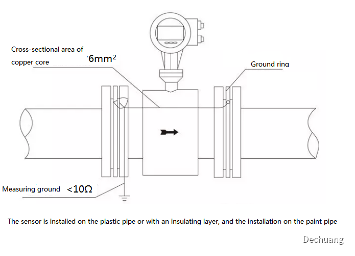
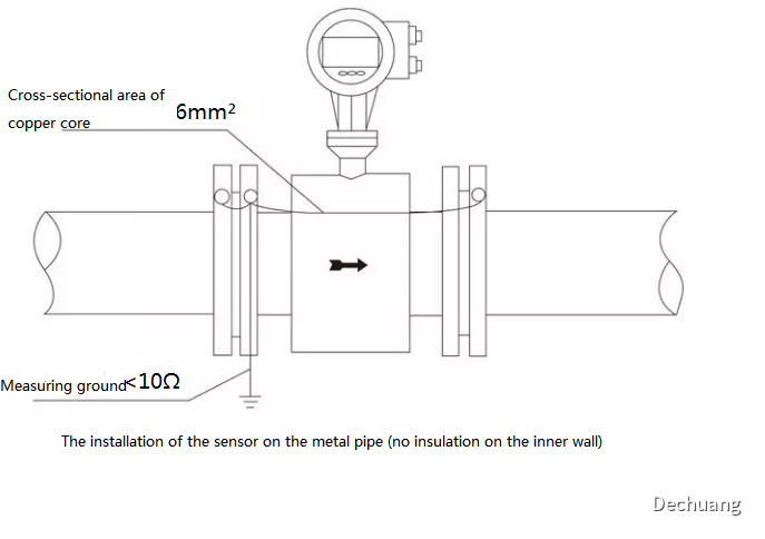
In order to make the meter work reliably, the flow signal generated by the sensor is very weak, usually in the microvolt or millivolt level. Preventing the influence of external electrical interference is an important factor in the good use of the flow meter, and grounding is a very effective measure to solve the impact of electrical interference. Therefore, the sensor should have a good separate grounding wire with a grounding resistance of <10Ω. If the pipeline connecting the sensor is coated with an insulating layer or a non-metallic pipeline, grounding rings or built-in grounding electrodes should be installed on both sides of the sensor.
Grounding method on metal pipe: The inner wall of the metal pipe has no insulating layer, so it is grounded as show below.
Grounding method on plastic pipes or on painted pipes with insulation layer: Grounding rings or built-in grounding electrodes should be installed on both ends of the sensor, so that the measured medium flowing in the pipe is short-circuited with the earth and has zero potential. Otherwise, the electromagnetic flow meter cannot work normally. (See below)